| Modified : april 16th. 2017 |
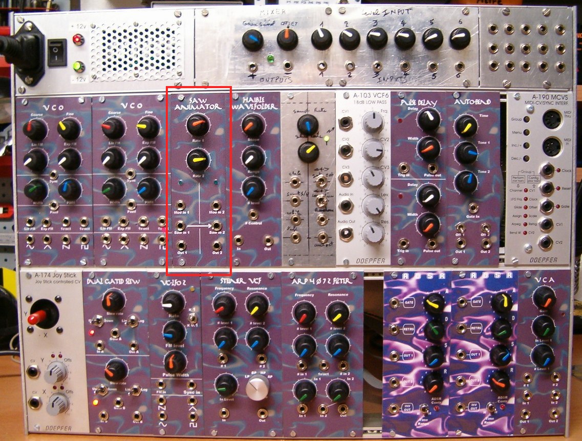
Saw Animator
|
En français
 |
 |
back to summary |
 |
 |
| Description |
| Modified : april 16th. 2017 |
Saw Animator
|
En français
|
|
back to summary |
|
|
| Description |
|
|
|
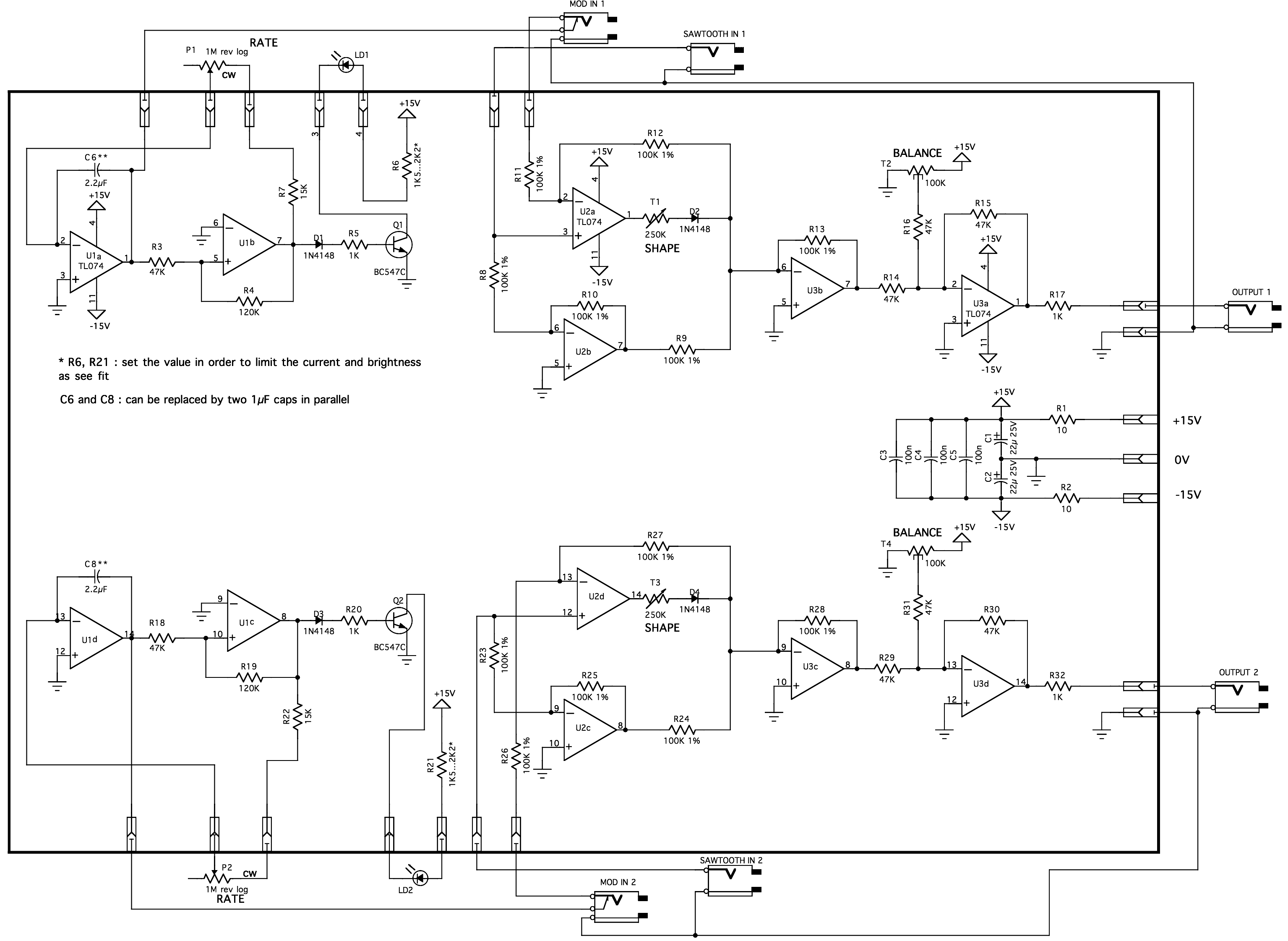
Schematic |
  |
|
IMPORTANT NOTE : the circuit has been
designed to work with balanced sawtooth signals ranging
from -5V to 5V, if you intend to use it with unbalanced
sawtooth or different peak to peak voltage you will have
to recalculate some resistor values...
|
|
|
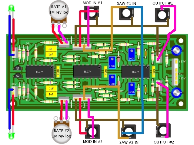
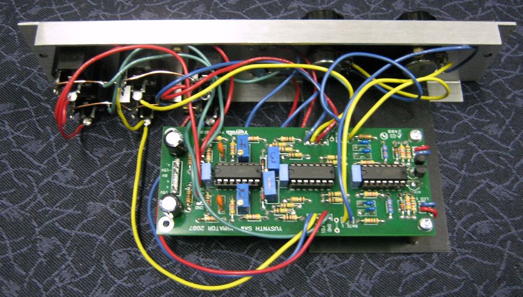
Printed Circuit Board and Component LayoutNOTE : the PCB and a component kit for this module are now available at Soundtronics.co.ukFor this PCB I used a double-layer design but you may etch a single face PCB and add a few straps as explained : solder a wire on the track side between the free pad of R22 and the pad of pin 3 of U4, solder a wire on the track side between the free pad of R45 and the pad of pin12 of U4. |
|||
|
|
|
List of parts and building instructions
|
|||||||||||||||||||||||||||||||||||||||||||||||||||||||||||||||||||||
|
|||||||||||||||||||||||||||||||||||||||||||||||||||||||||||||||||||||
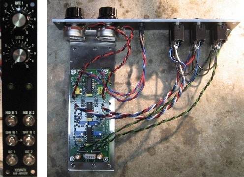
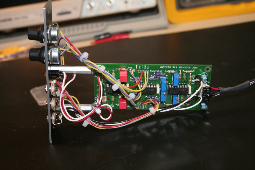
| Wiring |
|||||||||||||||||||||||||||||||||||||||||||||||||||||||||||||||||||||
 |
|
|
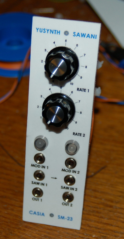
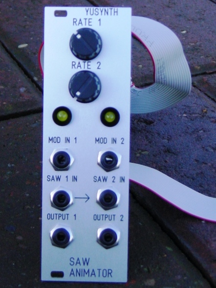
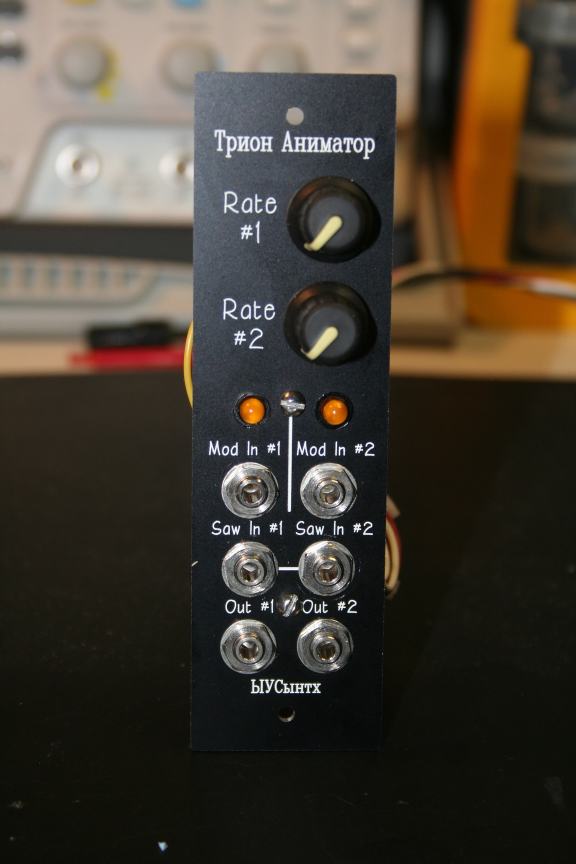
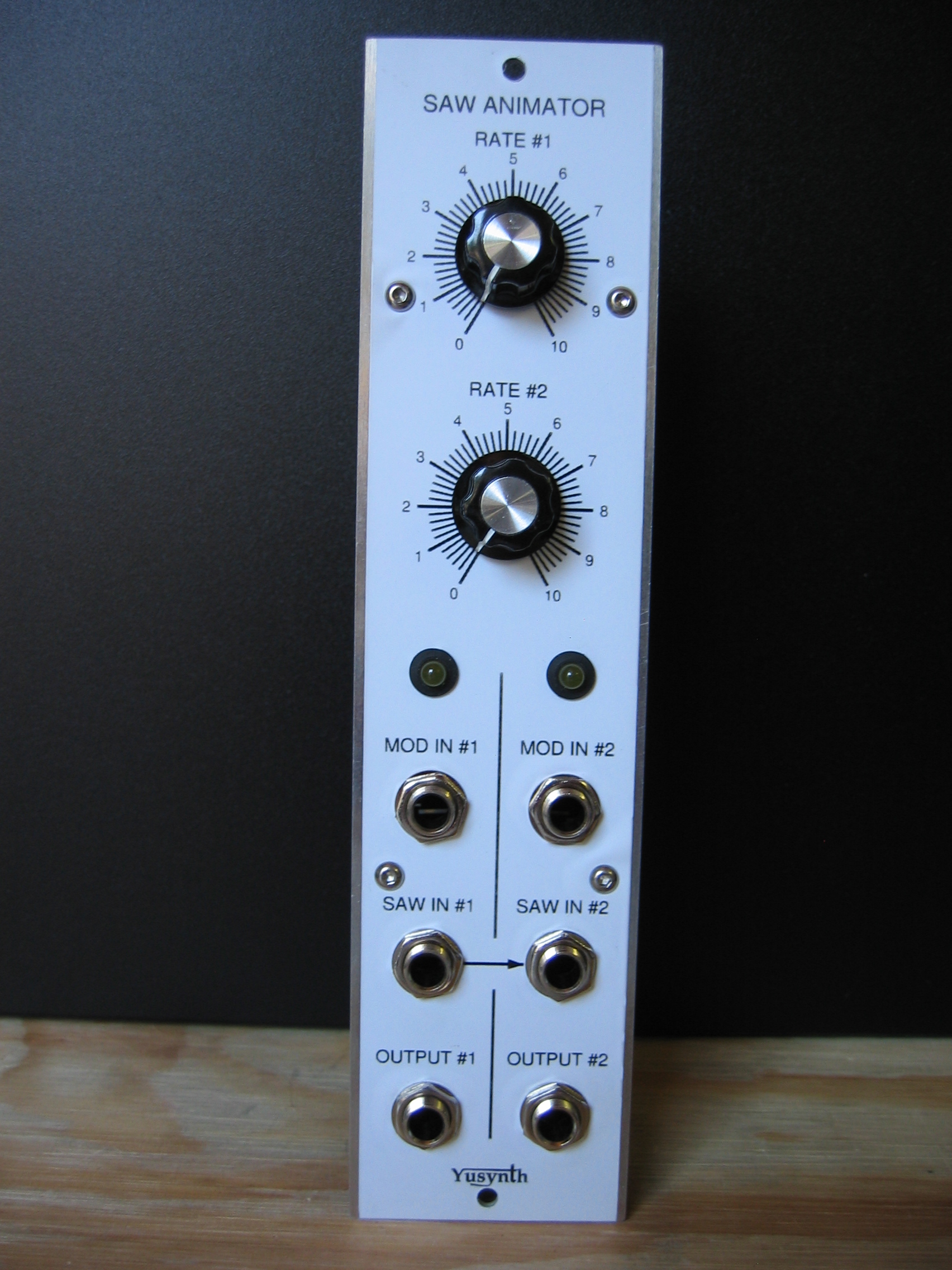
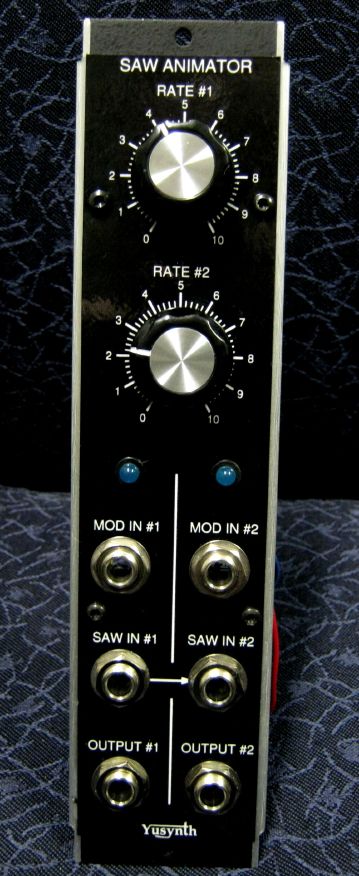
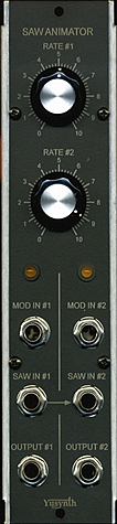
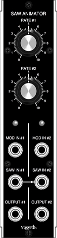
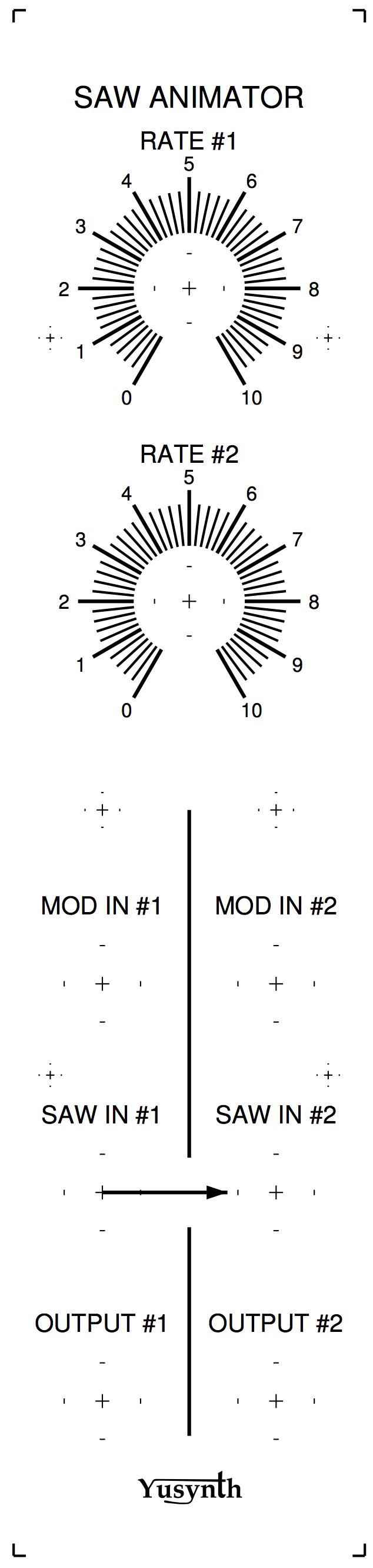
| Front plate |
||
|
|
|
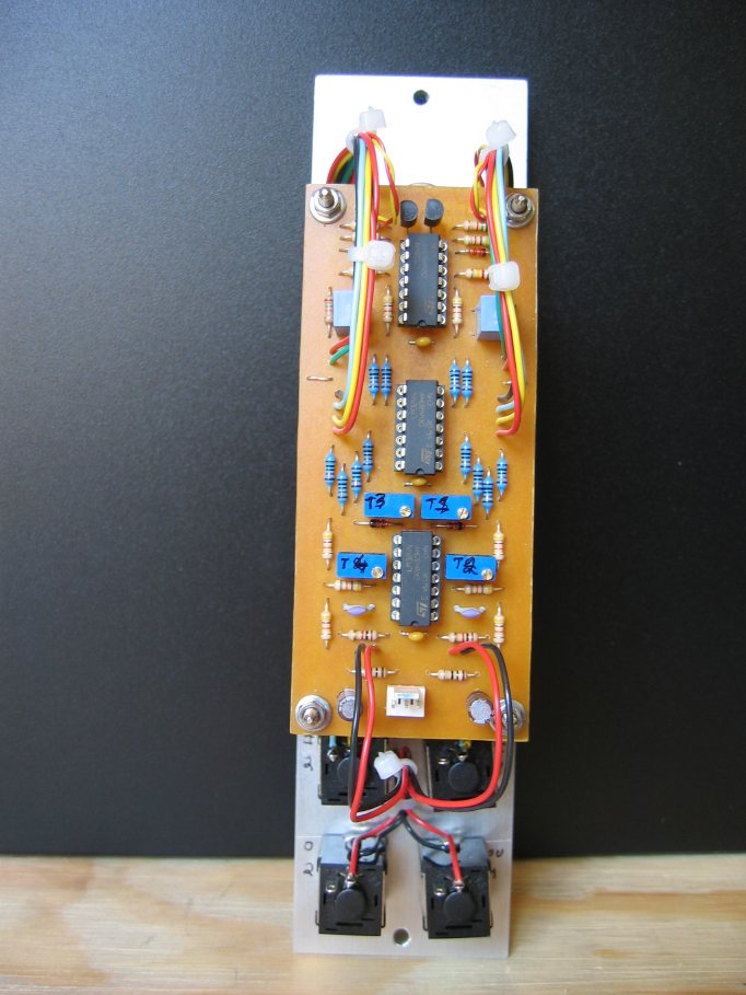
Trimming
|
| There are four trimmers
to be adjusted. Note that the adjustment procedure is
the same for T1 and T3 and for T2 and T4. Setting of T1 (SHAPE trimmer).
Setting of T2 (BALANCE trimmer)
Unground the MOD IN #1, you must see the sawtooth swaying at the rhythm of the internal LFO Repeat the same settings to adjust T3 and T4. |
|
|
References |
Bernie Hutchins ,
JAES 1981 "Analog circuit for Sound Animation", and
Electronotes #87  Digisound 80 Modular, Waveform multiplier Scott Bernadi's, Obesifier Waveform Animator, OG3 synth Elektor november 1982, (french version only !) |
 |
|
 |
| Name : Louis
van Dompselar Pseudo : Etaoin Modular project : Casia MS01 Location : Utrecht, Netherlands Website : www.casia.org/modular |
Name :
Patrick Pseudo : Baronrouge Modular project: JHC live lab Location: Toulon, France Web site : http://myspace.com/patjhc |
Name :
Paul Darlow Pseudo : Krisp1 Modular project: Krisp1 Location: Web site :http://www.krisp1.com |
 |
  |
  |
| Name: Bill and Will Pseudo: 'ills Modular Project: Dragonfly Alley Location: New Jersey, USA Website: dragonflyalley.com |
Name: David M. Ingebretsen Pseudo: digembre Modular Project: Location: Salt Lake city, USA Website: www.xmission.com/~dingebre |
Name : Frédéric Monti Pseudo : zarko Modular project : Location : Gardanne, France Website : |
  |
||
| Name : Steven Brenner Pseudo : Modular project : Location : Waterloo, Ontario, Canada Website : |
|
|||
|
|


