reference
|
value
|
number
|
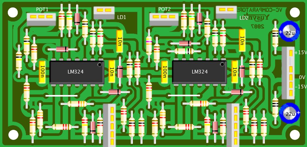
U1,U2
|
LM324
|
2
|
D1,D2,D3,D4,D5,D6,D7,D8,D9,D10
|
1N4148
|
10
|
R1,R2
|
10 ohm
|
2
|
| R16,R18,R20,R36,R38,R40 |
1K
|
6
|
R15,R17,R19,R35,R37,R39
|
1.2K
|
5
|
R21,R41
|
1.5K
|
2
|
R13,R14,R33,R34
|
3.3K
|
4
|
| R3,R22,R23,R42 |
10K
|
4
|
| R7,R8,R9,R10,R27,R28,R29,R30
|
12K
|
8
|
R25
|
47K
|
1
|
| R5,R6 |
100K * these values may be adjusted to obtain a
different threshold range
|
2
|
| R11,R31 |
150K
|
2
|
| R12,R32 |
220K
|
2
|
| R4,R24,R26 |
1M
|
3
|
C3,C4,C5,C6
|
10nF
|
4
|
C7,C8
|
100nF
|
2
|
C1,C2
|
22µF/25V electro.
|
2
|
P2
|
100K lin potentiometer
|
1
|
P1
|
250K/220K lin potentiometer
|
1
|
LD1,LD2
|
orange LED
|
2
|
Jk1,Jk2,Jk3,Jk4,Jk5,Jk6,Jk7,Jk8,Jk9
|
6.5 mm jack socket
|
9
|
|


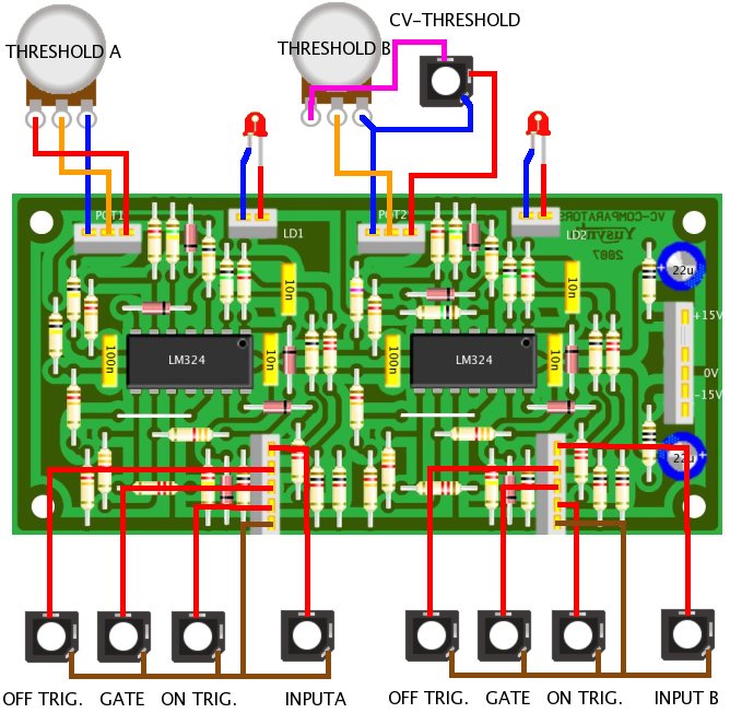
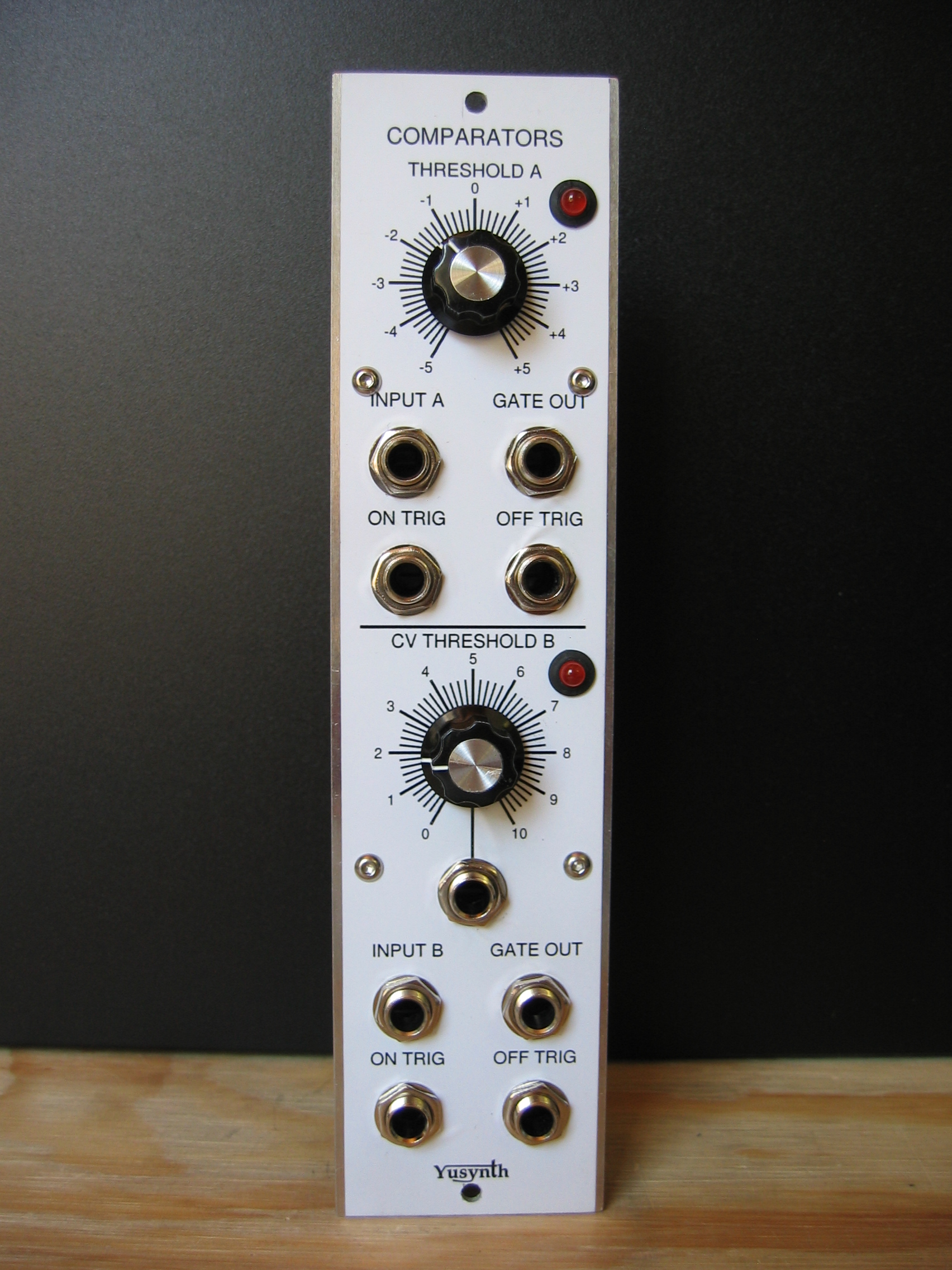
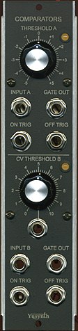
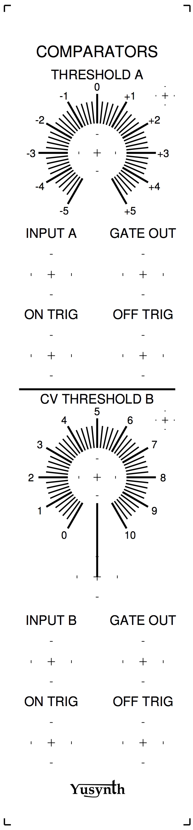
 This
COMPARATORS module is very useful utility module to create GATE signal
and pulses
from another source of signal. It can be used either to process
modulation CVs or audio signal (
This
COMPARATORS module is very useful utility module to create GATE signal
and pulses
from another source of signal. It can be used either to process
modulation CVs or audio signal (

