| Updated : jan. 30th, 2016 | ARP VCF |
En français
 |
 |
back to summary |
 |
 |
| Description |
| Updated : jan. 30th, 2016 | ARP VCF |
En français
|
|
back to summary |
|
|
| Description |
|
|
|
Schematics |
|
 |
| The
heart of this circuit is based on the EFM-VCF7b (which is
an adaptation of the original ARP-4072 VCF). I have added
two inverter buffer stages, one for the input signal (U2a)
and one for the output signal (U2b). The second stage
(U2b) plays also another part? In fact it is used as a
adder inverter which adds the signal taken after the
resonance potentiometer (through R43) to the direct output
signal (through R40). This trick is used to increase
the gain of the final stage and to compensate the drop of
the signal when the resonance is cranked up. You may use simple PNP transistors such as BC557 or 2N3906. The only thing is that you will have to match the NPN by pairs downto 2mV VBE and take care of the pin outs which are different for BC557 and 2N3906. |
|
|
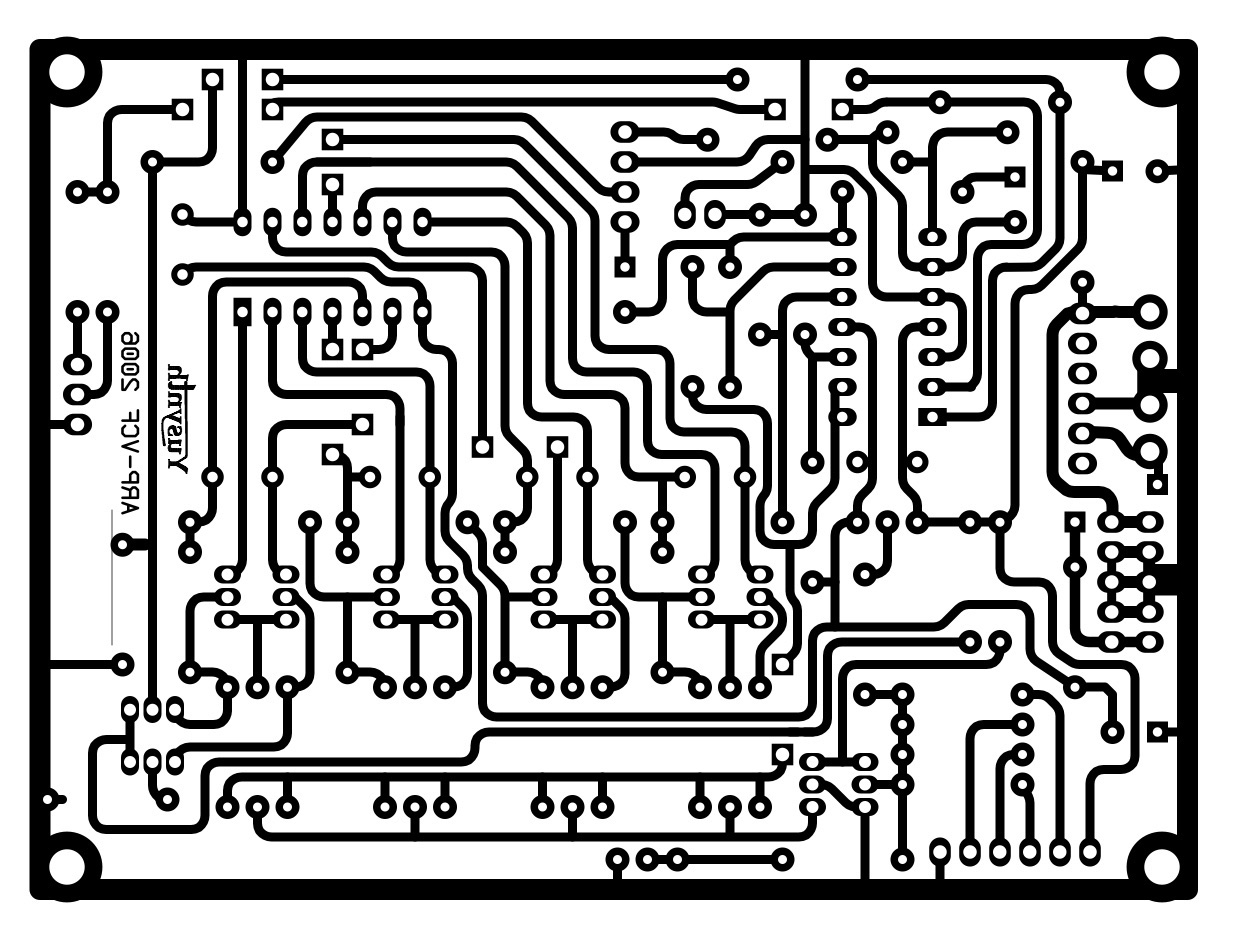
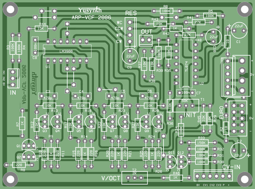
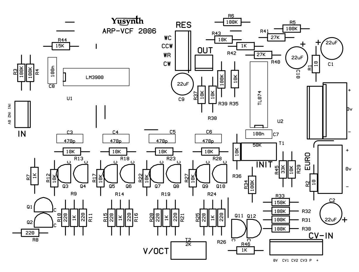
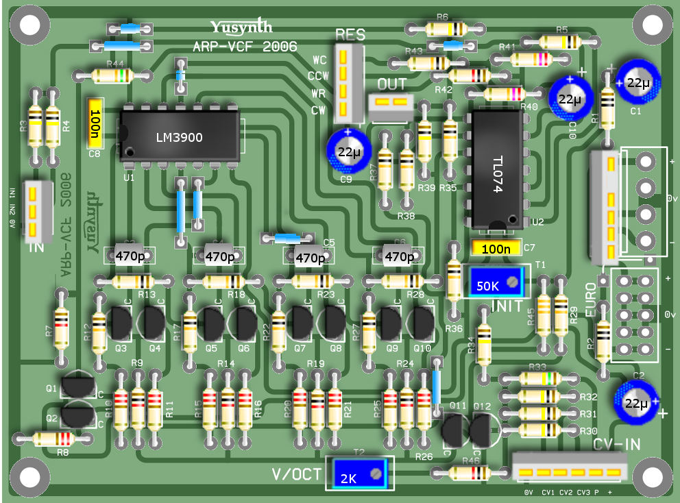
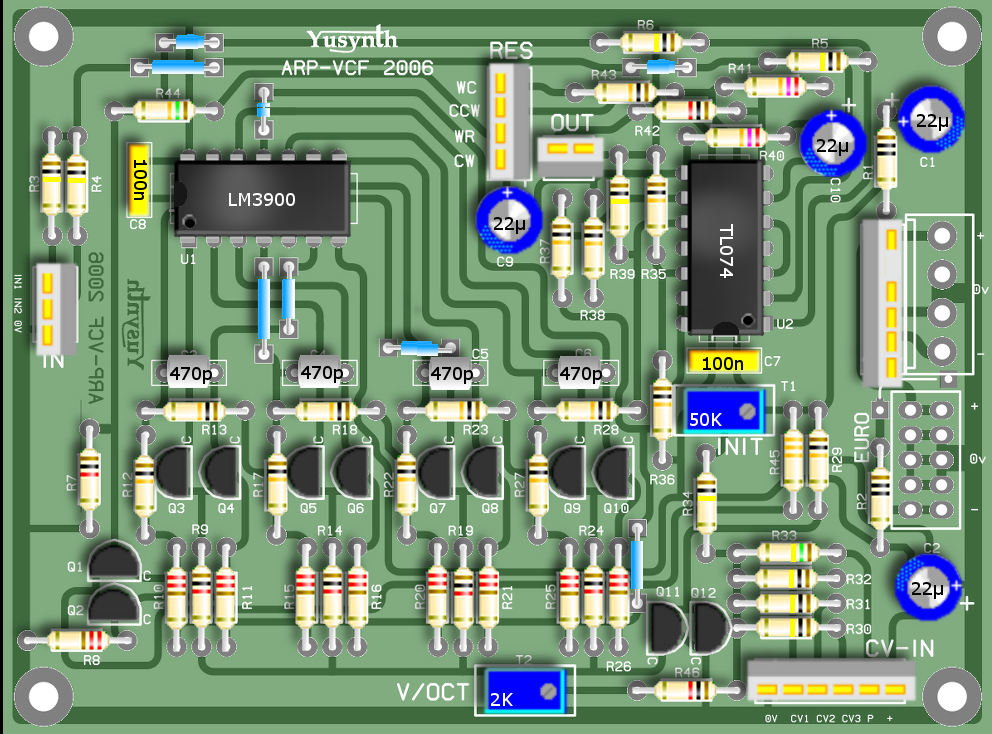
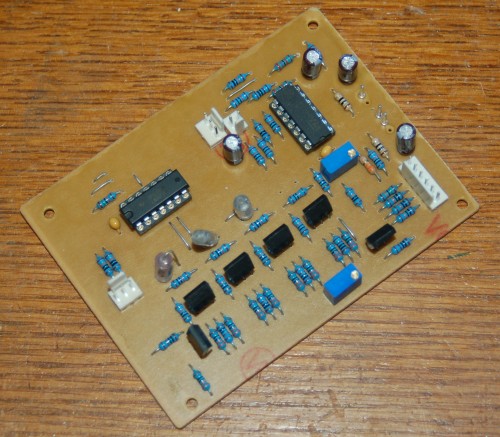
Printed circuit boards and component layoutsNOTE : the PCB and a component kit for this module are now made available by Soundtronics |
|||
|
|
|
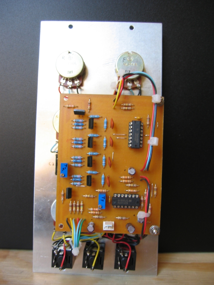
Building details |
||||||||||||||||||||||||||||||||||||||||||||||||||||||||||||||||||
|
||||||||||||||||||||||||||||||||||||||||||||||||||||||||||||||||||
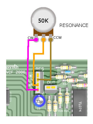
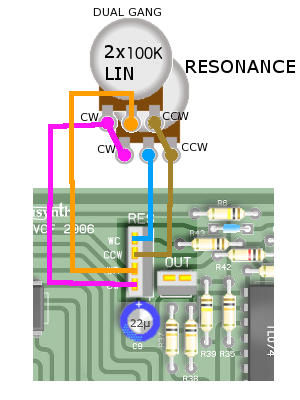
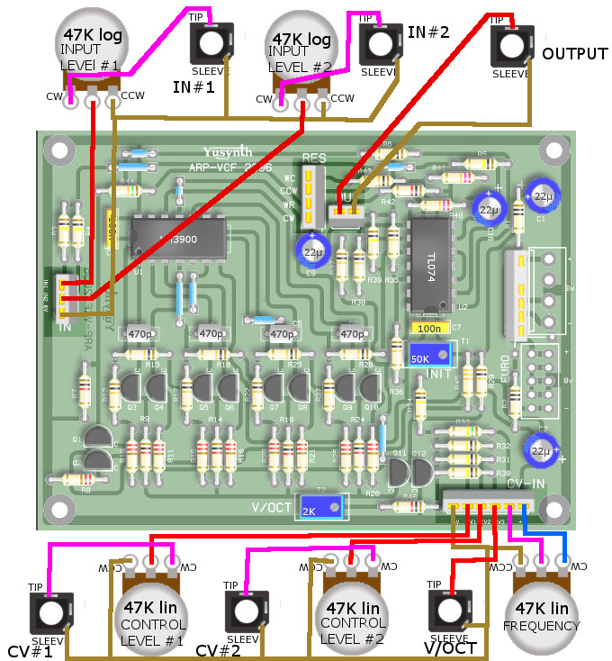
| Wiring |
||||||||||||||||||||||||||||||||||||||||||||||||||||||||||||||||||
| General
wiring |
||||||||||||||||||||||||||||||||||||||||||||||||||||||||||||||||||
 |
||||||||||||||||||||||||||||||||||||||||||||||||||||||||||||||||||
|
|
|
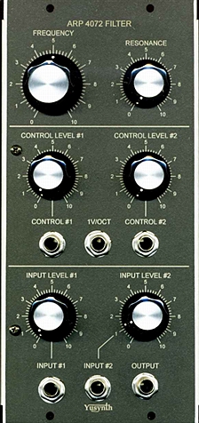
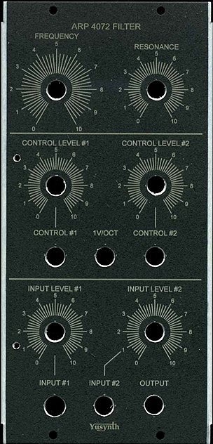
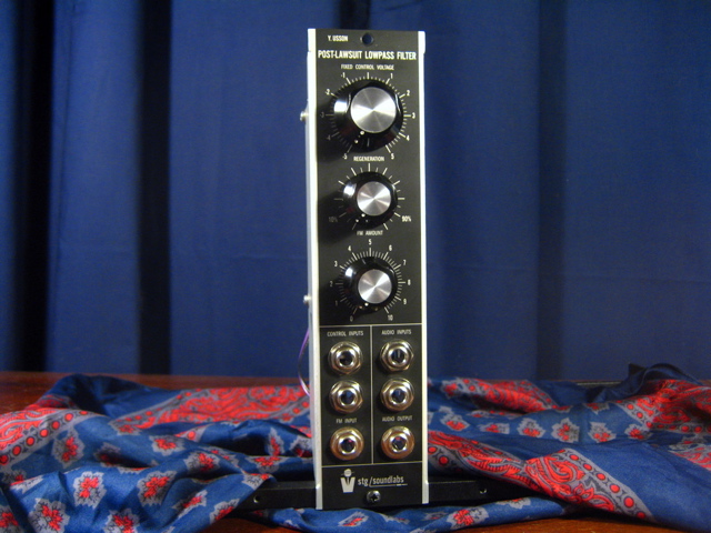
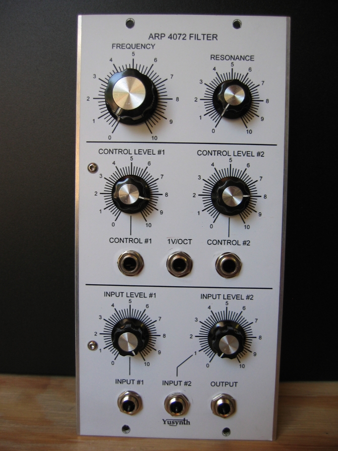
| Front
panel |
||
|
|
|
Trimming |
V/Octave tracking :
Optional settings
|
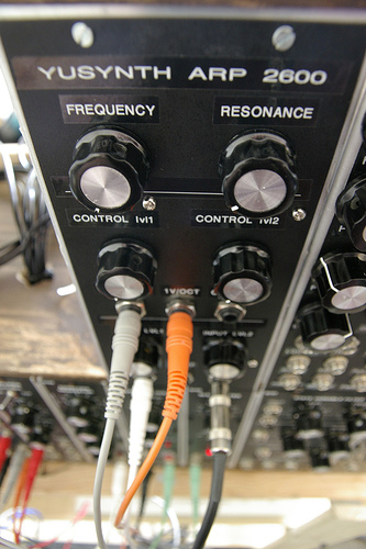
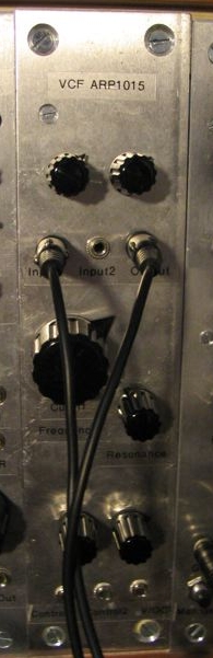
| Thanks to Thalassa77, here is
comparison of the Yusynth ARP clone and the genuine
ARP 4075 filter. |
|
|
References |
Here are
interesting links where to find schematics and infos
about the ARP VCF :
|
 |
 |
 |
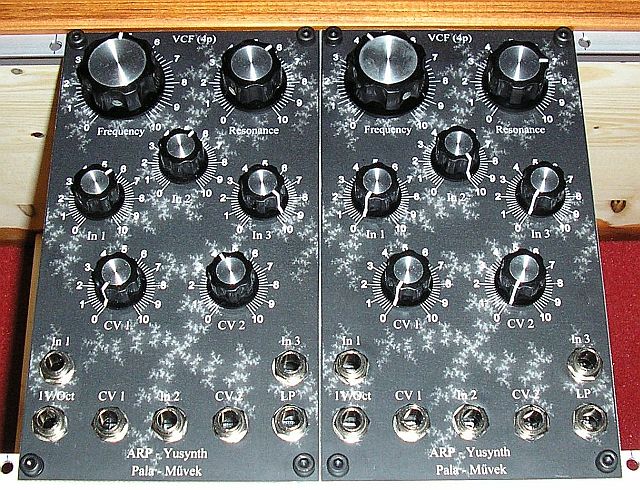
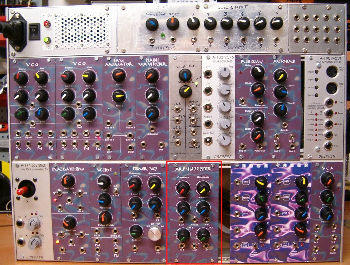
| Name : Gergö
PALATINSZKY Modular project : Fractal / Frakta'l Location : Budapest, Hungary Website : What a nice front panel indeed ! |
Name : Wasubot Modular project : Location : Australia Website : |
Name : Czaba ZVEKAN
Modular project : Location : Basel, Switzerland Website : |
 |
 |
 |
| Name
: Pseudo : Etaoin Modular project : Casia MS01 Location : Utrecht, Netherlands Website : www.casia.org/modular |
Name
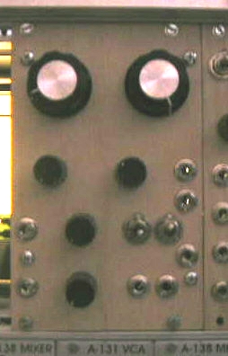
: Suit and Tie Guy Pseudo : Modular project : STG-Soundlab Location : Chillicothe, USA Website :www.suitandtieguy.com |
Name
: Pseudo : Funky40 Modular project : Location : Switzerland Website : |
 |
  |
|
| Name
: Patrick Pseudo : Baronrouge Modular project: JHC live lab Location: Toulon, France Web site : http://myspace.com/patjhc |
Name
: Frederic Monti Pseudo : Zarko Modular project: Location: Gardanne, France Web site : |
|
|||
|
|