| Updated : sep 29th, 2013 | MiniMoog VCF |
En français
 |
 |
back to summary |
 |
 |
| Description |
| Updated : sep 29th, 2013 | MiniMoog VCF |
En français
|
|
back to summary |
|
|
| Description |
|
|
|
Schematics |
|
 |
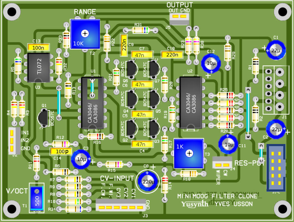
| For
Eurorack R24 and R27 must be changed to 220K et R26 to 1K |
|
|
|
|
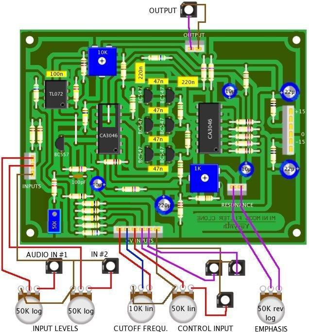
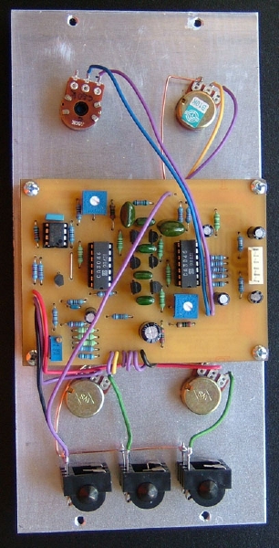
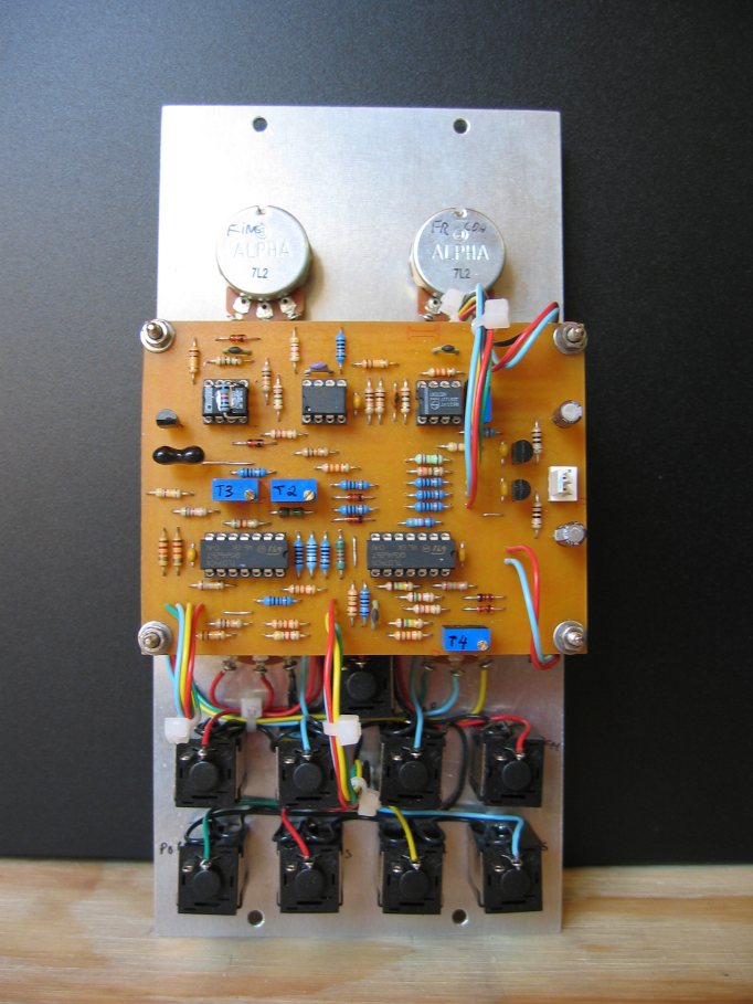
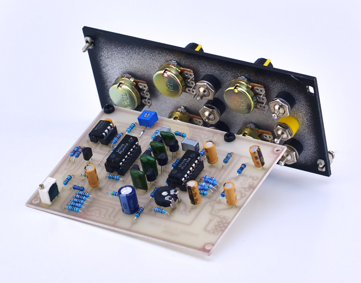
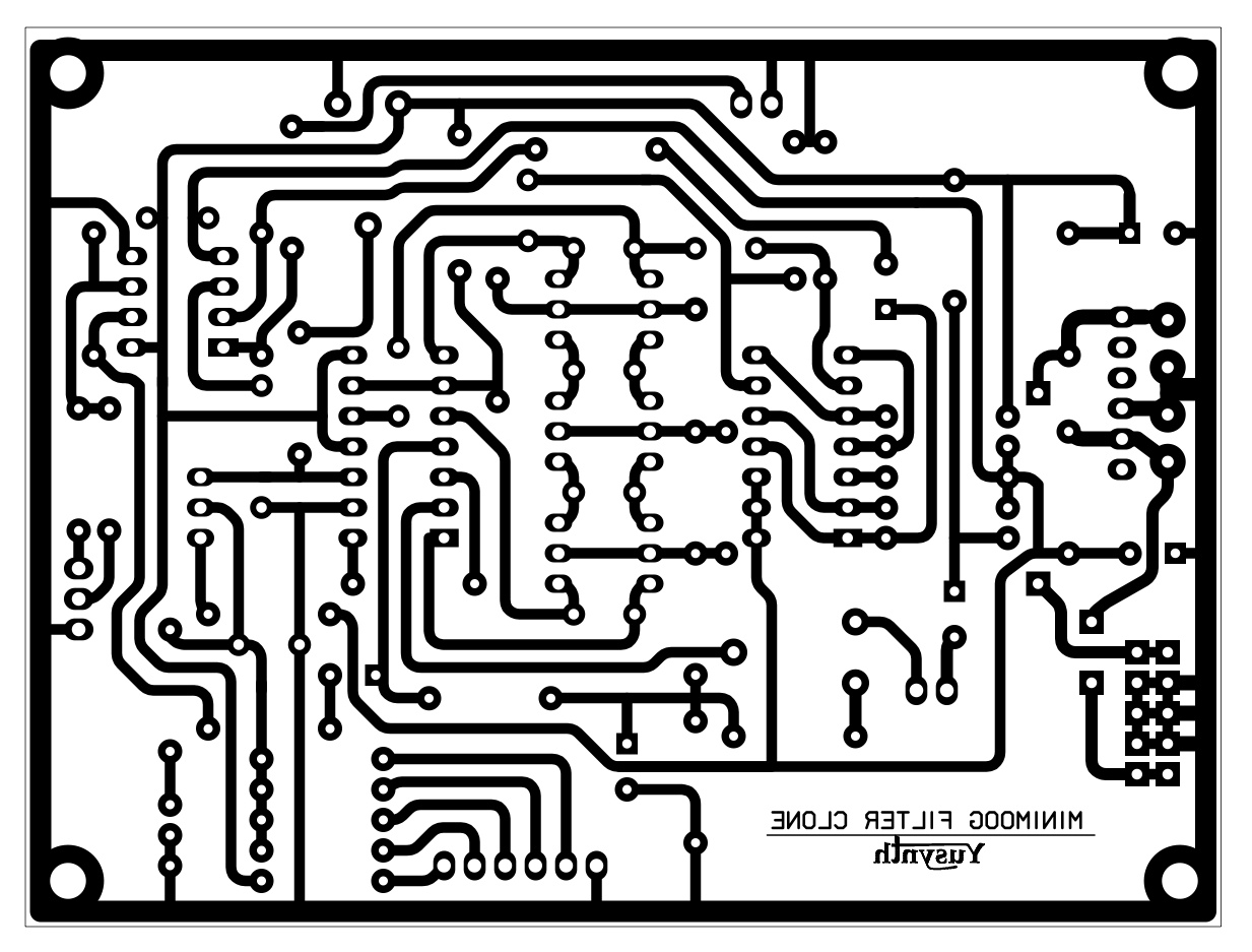
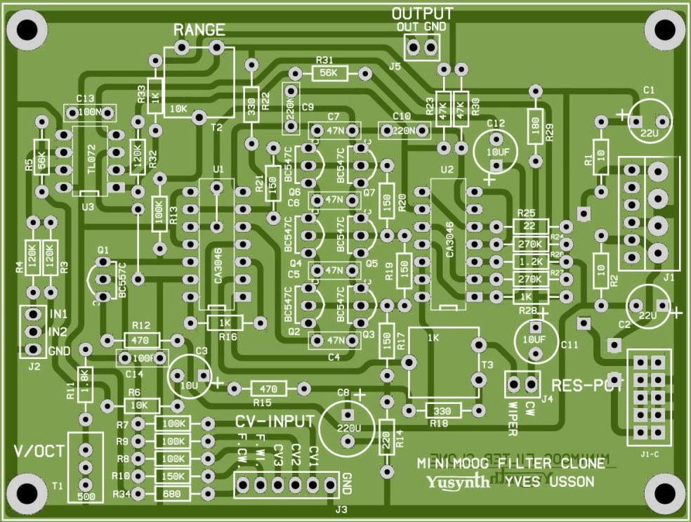
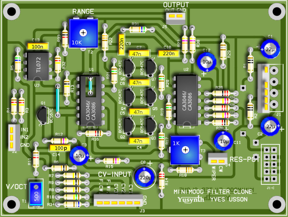
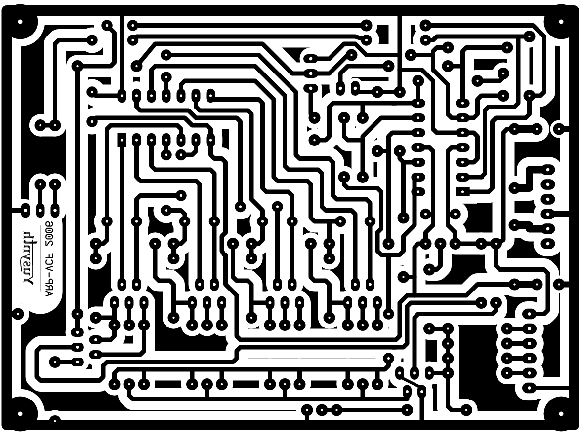
Building details |
||||||||||||||||||||||||||||||||||||||||||||||||||||||||||||||||||||||||||||||||||||||||||||||||||||||||||||||||||
|
||||||||||||||||||||||||||||||||||||||||||||||||||||||||||||||||||||||||||||||||||||||||||||||||||||||||||||||||||
| Do not forget to solder the two straps, one is located beneath U2 ! | ||||||||||||||||||||||||||||||||||||||||||||||||||||||||||||||||||||||||||||||||||||||||||||||||||||||||||||||||||
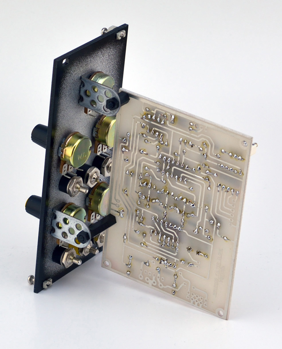
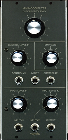
| Wiring |
||||||||||||||||||||||||||||||||||||||||||||||||||||||||||||||||||||||||||||||||||||||||||||||||||||||||||||||||||
 |
|
|
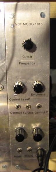
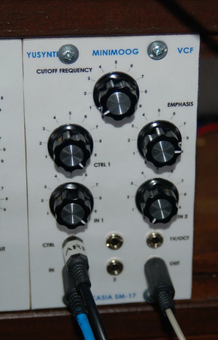
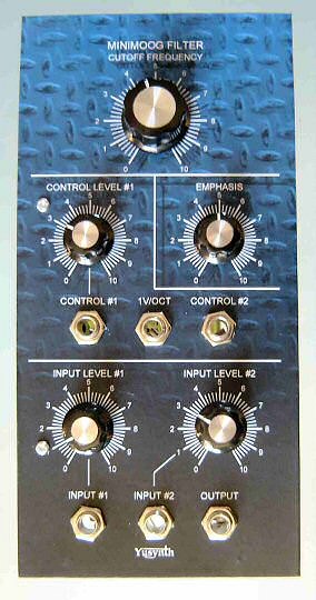
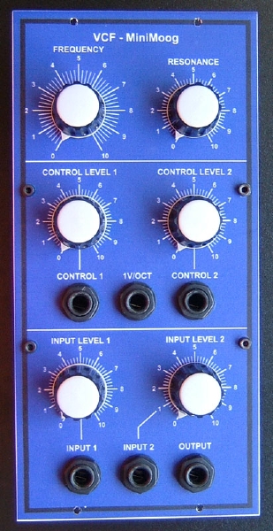
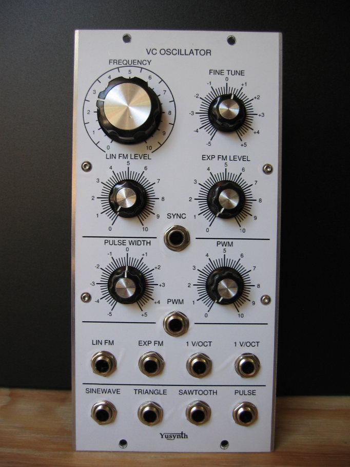
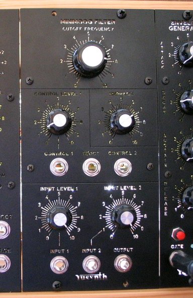
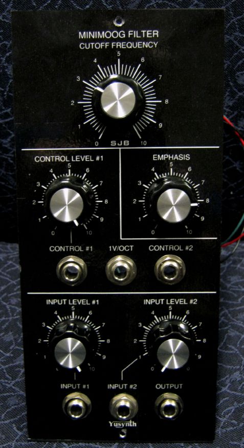
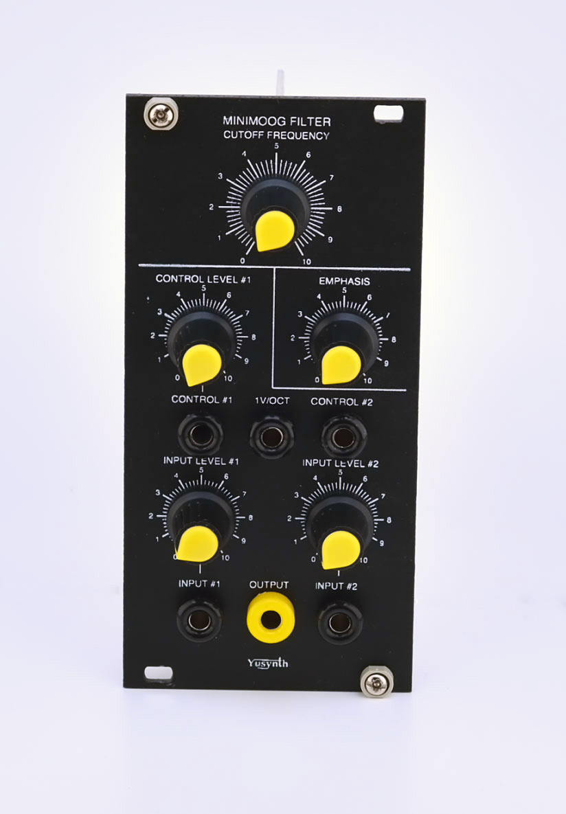
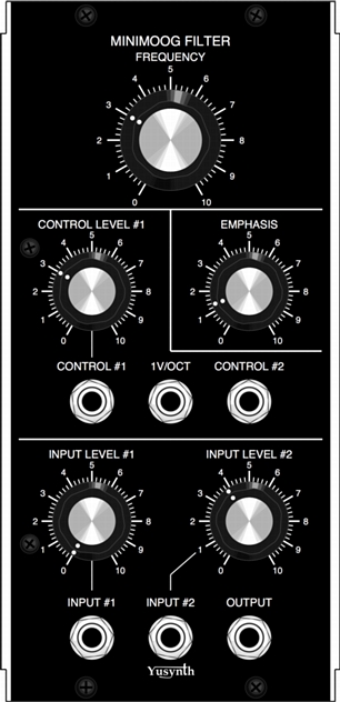
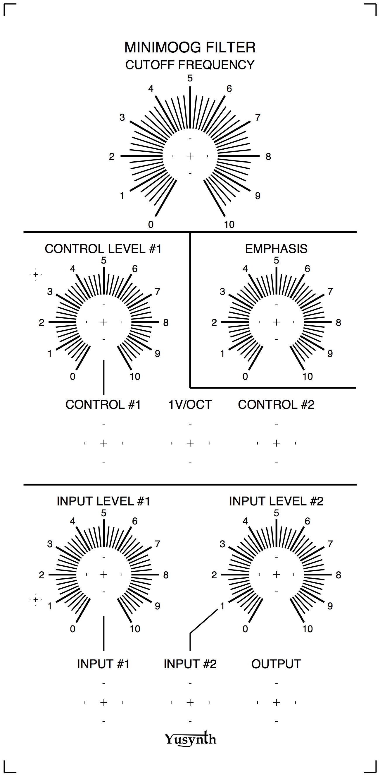
| Front
panel |
||
|
|
|
Trimming |
V/Octave tracking :
|
|
|
References |
Here are
interesting links where to find schematics and infos
about the Minimoog VCF :
|
 |
 |
 |
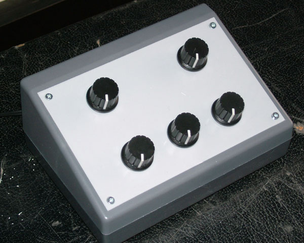
| Name : Czaba
ZVEKAN Modular project : Location : Basel, Switzerland Website : |
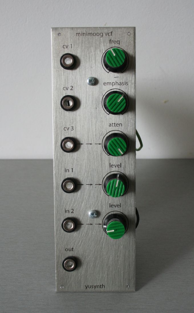
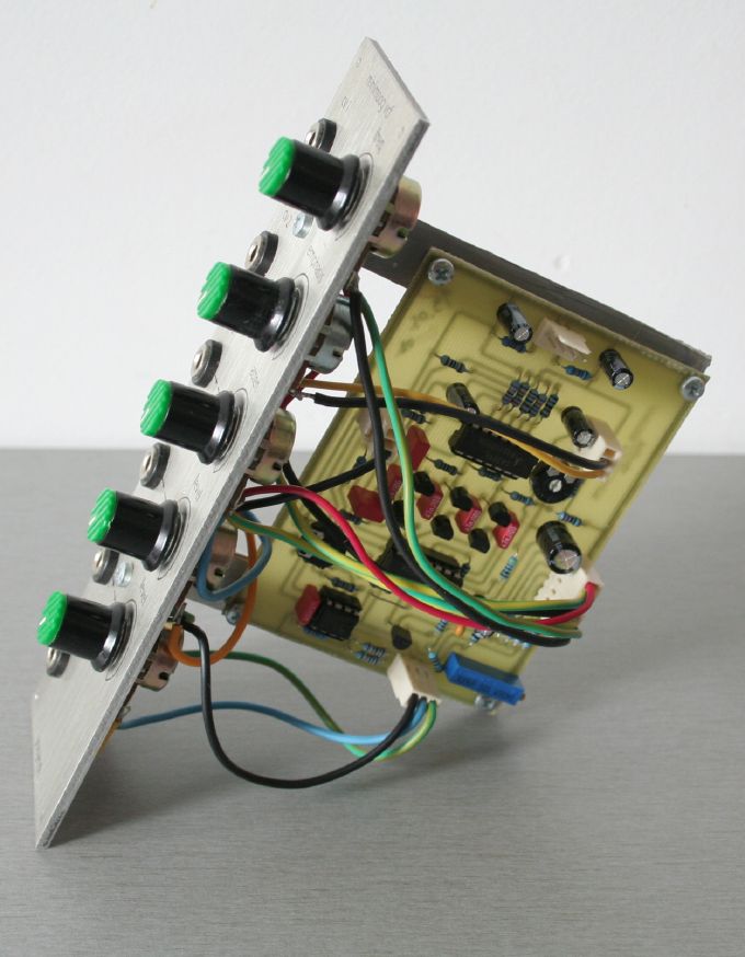
Name :
Jan CZMOK Modular project : Bastelstube Location : Germany Website : http://diy.czmok.de |
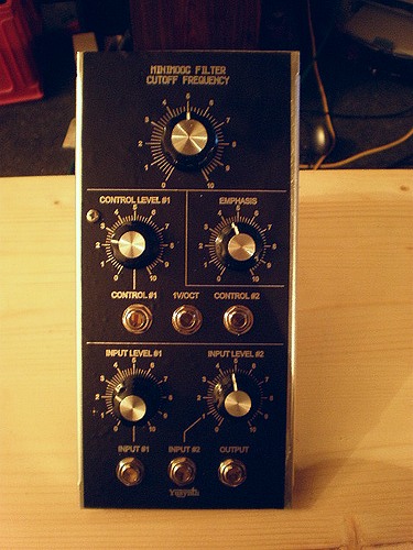
Name :
Pseudo : Etaoin Modular project : Casia MS01 Location : Utrecht, Netherlands Website : www.casia.org/modular |
 The VCF module is integrated in an effect device with an envelope follower |
  |
 |
| Name
: Pseudo : Sebo Modular project : Location : Argentina Website : http://www.cosaquitosenglobo.com.ar |
Name
: Ivan Pseudo : Modular project : greta1 Location : Zagreb, Croatia Website : |
Name
: Julien Pseudo : Modular project : Location : Website : |
 |
  |
 |
| Name
: François Labarre Pseudo : Blups Modular project : Location : Amiens, France Website : http://www.myspace.com/cromthewindingstar |
Name
: Pseudo : Sebo Modular project : Location : Argentina Website : http://www.cosaquitosenglobo.com.ar |
Name
: Julien Pseudo : Modular project : Location : Website : |
  |
 |
  |
| Name
: Zarko Modular project : Location : Gardanne, France Website : |
Name
: Pseudo : Tudy Modular project : Yusynth 17U Location : Brno, Czech Republic Website :www.insania.freemusic.cz |
Name
: Steven Brenner Pseudo : Modular project : Location : Waterloo, Ontario, Canada Website : |
   |
 |
|
| Name
: Peter Hostermann Modular project : Location : Germany Website : http://www.peter-hostermann.de |
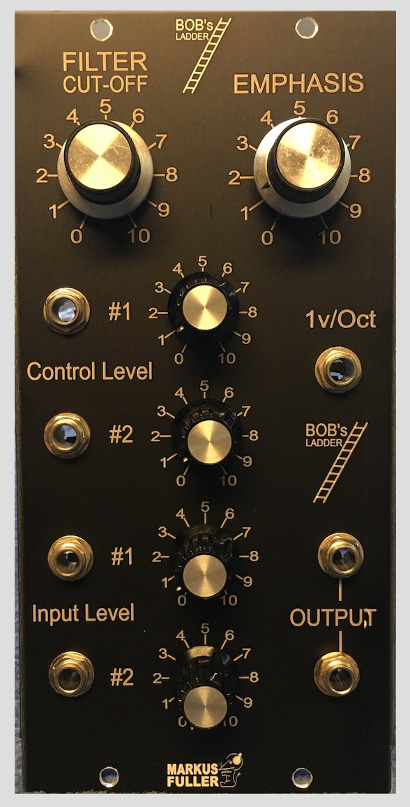
Name: Markus Fuller Location: Brighton, UK Website : http:/www.markusfuller.com |
|
|||
|
|
